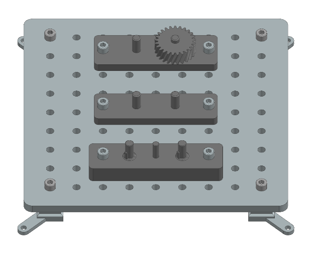
Assembly Instructions: Gear Assembly
This section provides step-by-step instructions for assembling the Gear Assembly task module of the Industrial Assembly Task Board. The module consists of various gear configurations that can be assembled and tested.
Task 1: 2 Gears
Step 1: Prepare the Components
3D-printed parts: |
Purchased components: |
|---|---|
2 Gears Mounting x 1 (Material: PETG) |
M8 Nut x 2 |
Gear 1 x 2 (Material: PETG) |
30mm M8 Screw x 2 |
Step 2: Manual Assembly of the 2 Gears Task
Align the two holes on the side of the Gear Mounting part with two suitable holes on the Taskboard. Then push two 30mm M8 Screws through the aligned holes and secure them from the bottom with M8 Nuts. Place the two Gear 1 parts next to the Taskboard.
Task 2: Helical Gear
Step 1: Prepare the Components
3D-printed parts: |
Purchased components: |
|---|---|
Helical Gear Assembly x 1 (Material: PETG) |
M8 Nut x 2 |
Helical Gear x 1 (Material: PETG) |
30mm M8 Screw x 2 |
Step 2: Manual Assembly of the helical Gear Task
Align the two side holes of the Helical Gear Assembly with two suitable holes on the Taskboard. Then insert two 30mm M8 Screws through the aligned holes and secure them from the bottom of the Taskboard with M8 Nuts. Finally, place the Helical Gear next to the Taskboard.
Task 3: 3 Gears
Step 1: Prepare the Components
3D-printed parts: |
Purchased components: |
|---|---|
3 Gears Mounting Part 1 x 1 (Material: PETG) |
M8 Nut x 2 |
3 Gears Mounting Part 2 x 1 (Material: PETG) |
40 mm M8 Screw x 2 |
Shaft with key x 2 (Material: PETG) |
|
Gear 3 x 1 (Material: PETG) |
|
Gear 3 with Groove x 2 (Material: PETG) |
Step 2: Manual Assembly of the 3 Gears Task Assembly
Place Mounting Part 2 facing down like shown in the picture.
Then place the two Shafts with Key parts into the two holes of Mounting Part 2.
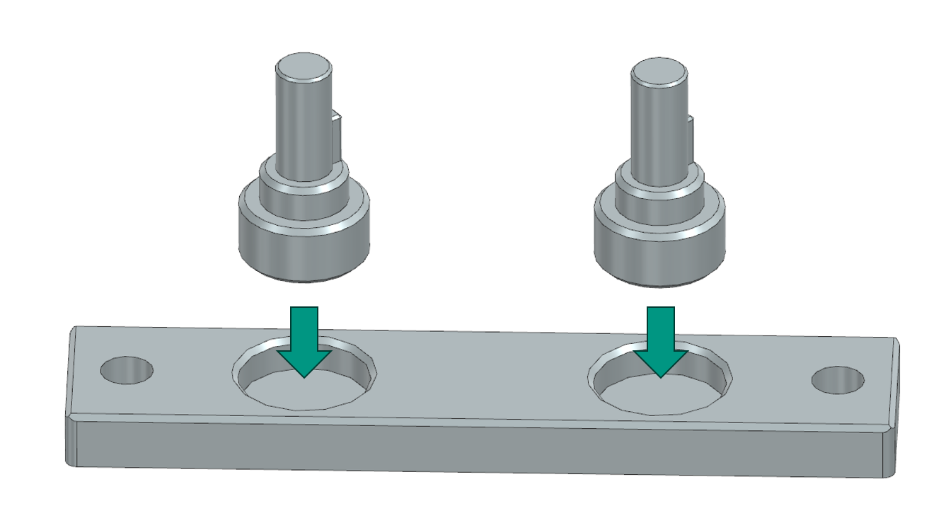
Next place the mounting part 1 on top of the assembled components, so that the two shafts stick out.
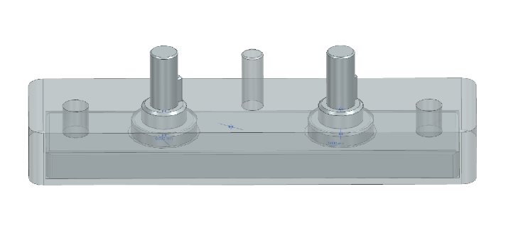
Place the assembled parts on the Taskboard holding them together, so that the two holes on the side of the assembly group line up with two holes on the Taskboard. Push the two 40 mm M8 Screws through the holes and fixate them from the bottom of the board using the M8 Nuts. Place the 3D-printed Gears, two with groove and one without next to the Taskboard on a flat surface graspable for the robot.